Home › Forums › MGTD Kit Cars › My Project › Building Alfred
- This topic has 228 replies, 23 voices, and was last updated 12 years, 1 month ago by
Steve Struchen.
-
AuthorPosts
-
December 17, 2012 at 5:05 pm #253054
Anyone know what the wheelbase of a CMC/Fiberfab Pinto-based car is?
December 17, 2012 at 5:10 pm #253055I’ll measure mine when I get home tonight.
Bill Ascheman
Fiberfab Ford
Modified 5.0, 5sp., 4:11
Autocross & Hillclimb
"Drive Happy"December 18, 2012 at 5:01 pm #253056Mine measures 93.5″
Bill Ascheman
Fiberfab Ford
Modified 5.0, 5sp., 4:11
Autocross & Hillclimb
"Drive Happy"December 18, 2012 at 8:40 pm #253057Makes sense. The donor Pinto was 94.2. Thanks for the measurement. I will use this to lay out my chassis.
December 28, 2012 at 2:12 pm #253058Received a plasma cutter for Christmas: a Locos 520D, which is also a TIG welder. I finally got to the point that I ran out of floor space, so first project it to make a welder cart that combines my old MIG, an Oxy-Acetylene and my chop saw.
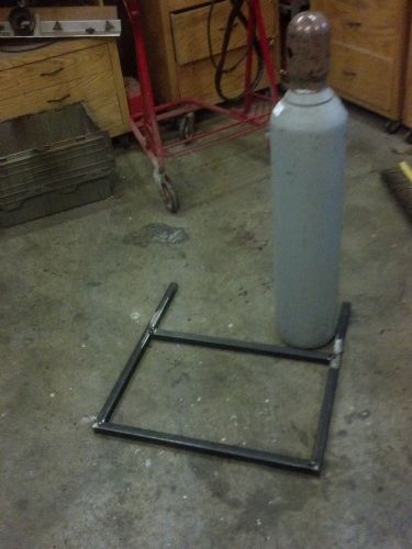
First step is to lay out for welder and bottles.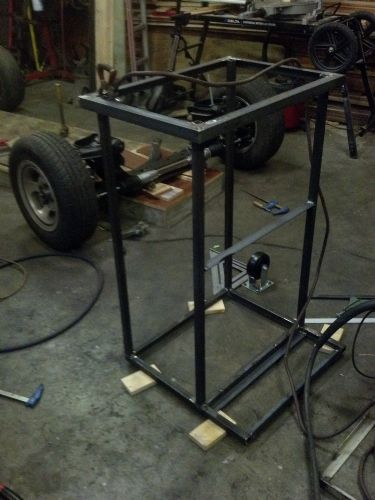
Looks like a frame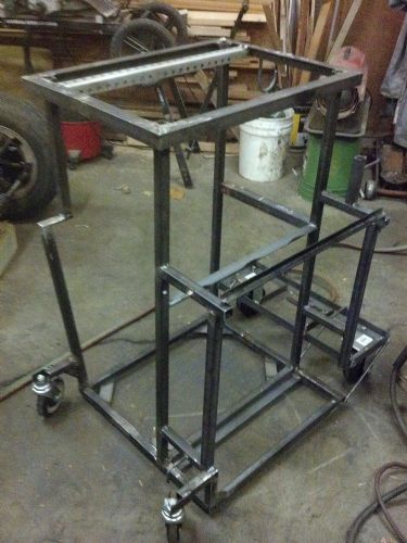
With wheels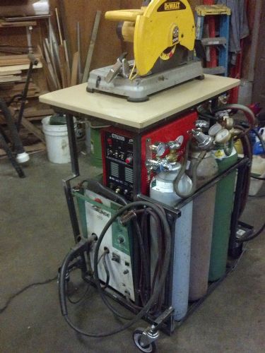
Loaded with chop saw on top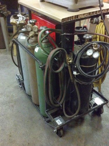
with Oxy/Acetylene setup around back. Now I can easily wheel all this in place and store it all back in place. Can start making an MG frame soon.December 28, 2012 at 2:18 pm #253059Nice work!
Gotta love having to build stuff…so that you can build other stuff!Paul Mossberg
Former Owner of a 1981 Classic Roadsters Ltd. Duchess (VW)
2005 Intermeccanica RoadsterIf you own a TDr and are not in the Registry, please go to https://tdreplica.com/forums/topic/mg-td-replica-registry/ and register (you need to copy and paste the link)
December 28, 2012 at 9:14 pm #253060Now, that is a great little work station.
Everything in one place but fully portable at the same time.Bill Ascheman
Fiberfab Ford
Modified 5.0, 5sp., 4:11
Autocross & Hillclimb
"Drive Happy"December 28, 2012 at 11:59 pm #253061The front wheels are from a shopping cart I and the rears are from Lowe’s. Both have ball bearings, so it rolls fairly easily, in spite of the weight of the stuff onboard. I estimate it to be close to 400 lbs total.
December 29, 2012 at 2:47 am #253062Very very nice.
December 29, 2012 at 9:19 pm #253063Progress. I spent all day getting the front square to the plywood frame platform and then getting the angles right for the front frame risers. Tomorrow I’ll use some pocket screws to hold these parts together.
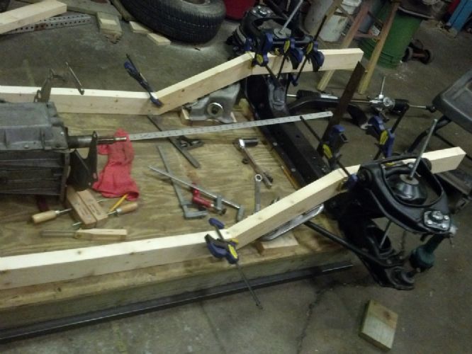
Next I need to work on the rear arch.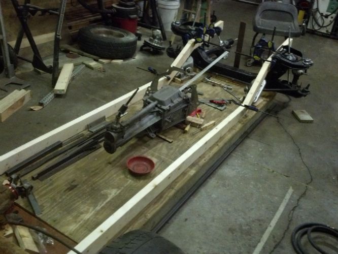 December 29, 2012 at 9:21 pm #253064
Man, they said these things had wood frames originally, but….:-)
December 30, 2012 at 3:52 am #253065I can’t tell from the photos as to what rear you’re running. As a note of caution, the popular 6-3/4″ ring gear used in the Pinto is rather weak. Once I hotrodded my motor I started blowing those things apart. Don’t know what your plans are other than a larger engine, but please consider a beefier component for your build.
Bill Ascheman
Fiberfab Ford
Modified 5.0, 5sp., 4:11
Autocross & Hillclimb
"Drive Happy"January 1, 2013 at 9:20 pm #253066That rear is just a placeholder. It came with my parts car. Yesterday I bought a rear from a 76 Cobra II, a Ford 8″. Looks a lot beefier.
January 2, 2013 at 3:23 am #253067Yep, that’s the one to go with. That was used all through the sixties on real mustangs with V8’s. It’ll handle your planned V6. If the tag is still attached to the carrier bolts, the ratio should be stamped in the lower left corner. Mine was equipped with 3:40’s. When I swapped to a 5 speed I switched to 4:11’s. I still have that original carrier stored in a 5 gallon bucket of oil.
Bill Ascheman
Fiberfab Ford
Modified 5.0, 5sp., 4:11
Autocross & Hillclimb
"Drive Happy"January 2, 2013 at 8:05 am #253068Being hopelessly forever an engineer, I came up with a method to accurately measure the gear ratio. Raise one wheel and block the other. Let both wheels turn if you have posi. Make a mark (via masking tape and magic
marker) on each of rear yoke and diff housing. Put a piece of masking
tape around the entire tire and make a start mark using a chair or
something to point to the start mark on the tire. Turn the wheel until
the drive shaft makes exactly one turn. Make a second mark on the tire
masking tape for the distance the tire traveled. Cut off the tire
masking tape exactly at the start mark. Lay the tape straight and
measure the tire circumference (whole tape) and divide by distance tire
moved (second mark). Multiply by two. That’s the ratio. Don’t multiply
if you have posi.January 2, 2013 at 7:03 pm #253069You can simplify that by spinning the driveshaft once and seeing how many times the tire turns.
Bill Ascheman
Fiberfab Ford
Modified 5.0, 5sp., 4:11
Autocross & Hillclimb
"Drive Happy"January 2, 2013 at 8:55 pm #253070In short, that’s exactly what I said, move the driveshaft exactly one turn and measure how much less than one turn the tire moves. For example, on a 3.00 rear end the tire will move 1/3 of a revolution for a full turn of the driveshaft.
January 24, 2013 at 6:48 pm #253071It’s been a while since I made real progress. Problem was I needed to finish the design of the rear suspension. The driver was that it had to fit and also needed to change over from the MII 40″ leaf spring to smaller coil spring setup. Also had to fit either a three or four link with panhard within the confines of the room given under the package tray. Finally settled on three link without panhard, shown later.First pic shows after-market Mustang trailing arm with coil mount and also a tubular a-arm that serves both as third link and panhard.
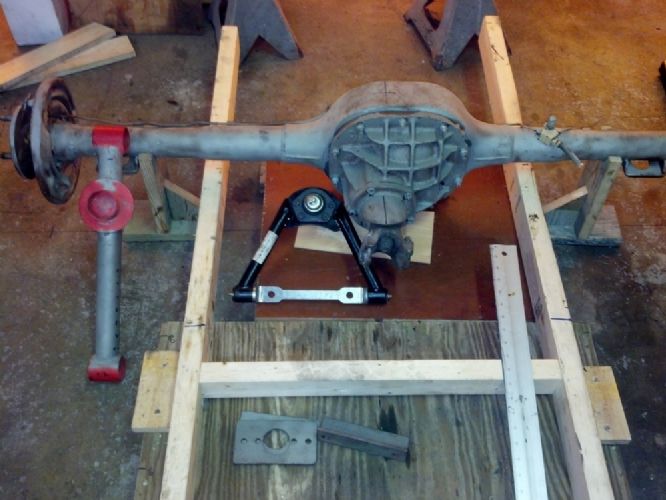
Next pic is a frame in pieces…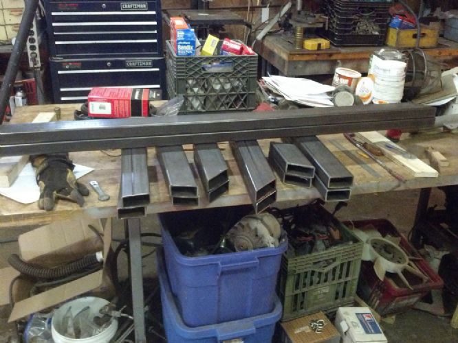
First weld…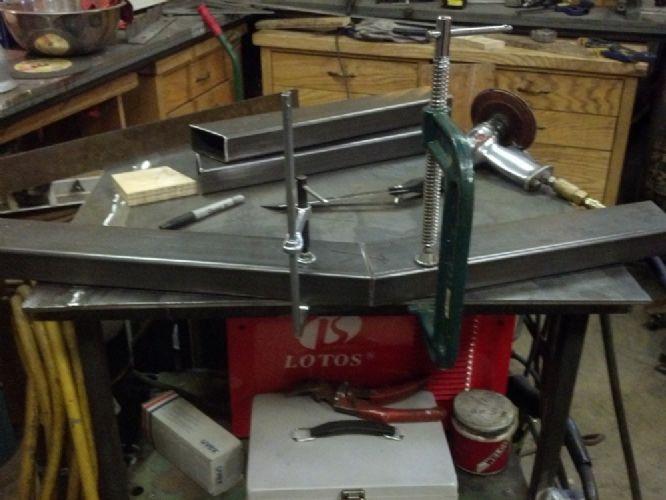 January 24, 2013 at 6:57 pm #253072
Did you (or do you) work in a high end garage? Race team? How did you acquire such skills? Wish you were my next door neighbor.
 January 24, 2013 at 6:57 pm #253073
One side of frame laid out and tacked together
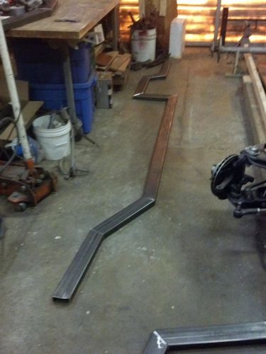
Welded the two frame sides.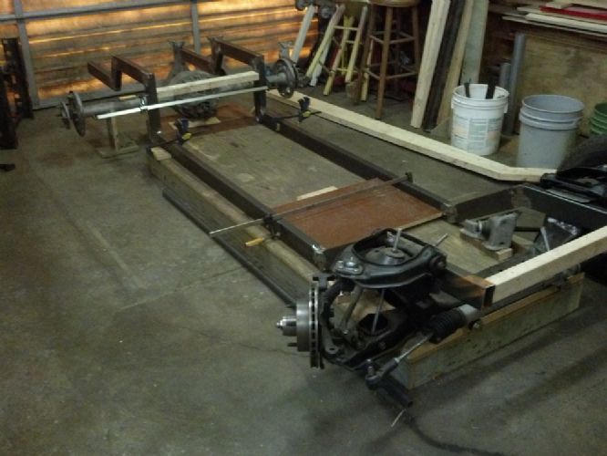
Bracket for Ford 8″ to hold a ball joint. This serves as the third link and makes a panhard unnecessary.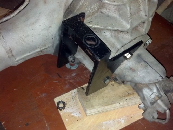
A-Arm from Speedway Race catalog, later will be bolted to a frame crossmember that I can only locate once lower trailing arms are done and pinion angle set. Long way from now….
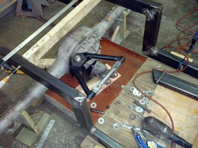
Side view…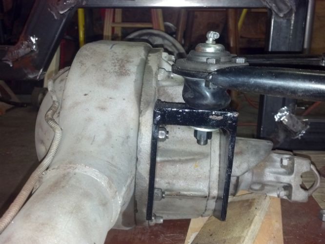 January 24, 2013 at 6:58 pm #253074
Did you (or do you) work in a high end garage? Race team? How did you acquire such skills? Wish you were my next door neighbor.
 January 24, 2013 at 7:01 pm #253075
Although I have rebuilt several old cars and trucks, some with serious body rust problems, this is my first frame. I am lucky to have a friend down the street who likes to build cars from scratch. I’m down there about twice a week with my progress and asking advice on the next step. It was his suggestion to use an A-arm instead of a panhard.
January 24, 2013 at 7:08 pm #253076Nice custom frame. That use of the control arm as an upper strut is really a novel approach. That should work really well with the addition of another crossmember. Beautiful.
Bill Ascheman
Fiberfab Ford
Modified 5.0, 5sp., 4:11
Autocross & Hillclimb
"Drive Happy"January 24, 2013 at 7:10 pm #253077I like the A-arm idea. Easy to source part, and the setup is not unlike what Jaguar did on the early C-Type to augment the torsion bars. Have you seen road-going hotrods with that setup?
January 24, 2013 at 7:10 pm #253078Got it! I wish your next door neighbor was my next door neighbor.
You’re doing really nice work. Are you going to do the welding or get your neighbor to do it? Rockyx’s son does super welding, but he’s in Fla. When I get done welding something, I hide it as quickly as I can. -
AuthorPosts
- You must be logged in to reply to this topic.
