Home › Forums › MGTD Kit Cars › My Project › Building Alfred
- This topic has 228 replies, 23 voices, and was last updated 12 years, 1 month ago by
Steve Struchen.
-
AuthorPosts
-
January 24, 2013 at 7:18 pm #253079
The tradeoff is to raise the roll center to the middle of the ball-joint. It might feel a little funny, or at least something new when I really push it in slalom turns. In return I get less parts, a tight rear suspension but still have room for double exhaust to wrap over the axles. A panhard would have been in the way. I could always replace with an adjustable A-arm if I want to fine tune the pinion angle.
Like this…
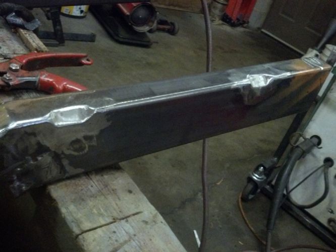
http://www.ebay.com/itm/IMCA-MODIFIED-STOCK-CAR-TUBULAR-ADJUSTABLE-UPPER-A-ARM-/360569093394?pt=Race_Car_Parts&hash=item53f397bd12&vxp=mtrJanuary 24, 2013 at 7:23 pm #253080I already welded the frame sides. My welds are ugly but I always grind an angle to let the weld penetrate. I have more metal as ground off filings on the garage floor than I do in the welds on the frame. I also added a reinforcing plate across the inside corner of each intersection since this is where the stresses are greatest.
January 25, 2013 at 9:12 am #253081Wow. And I thought mine was built from scratch. Loving the progress pictures.
January 25, 2013 at 11:41 am #253082January 25, 2013 at 11:44 am #253083To answer edsnova, I was told that Alpha had a similar setup, but their arm is located from behind creating what’s called a Watts link (look it up, real interesting). I considered locating behind as the angles are better, but had no room, it would have had to be 12″ and would have stuck out into the gas tank area.
January 25, 2013 at 5:56 pm #253084Yep, heard of the Watts link. Popular on the Mustangs, I think. The C-Type was more like what you’re doing, except the A-arm is turned the other way.
And it’s offset to one side.
January 27, 2013 at 12:16 am #253085January 27, 2013 at 12:23 am #253086Had to offset some because I didn’t have enough travel room in center with the driveshaft directly below. Not as much as the C type .My expert said a slight offset is still OK.
January 27, 2013 at 4:57 pm #253087Yeah, it should be fine. That C-Type rig was not so great anyway, which is why they changed it to a Panhard.
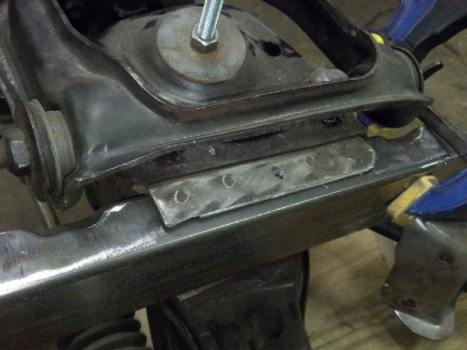
February 1, 2013 at 6:40 pm #253088Put a couple of chamfers into the frame to make room for the back of the upper A-Arms. If you look under the hood of Mustang II you will see the same chamfers in the unibody frame.
 February 1, 2013 at 6:44 pm #253089
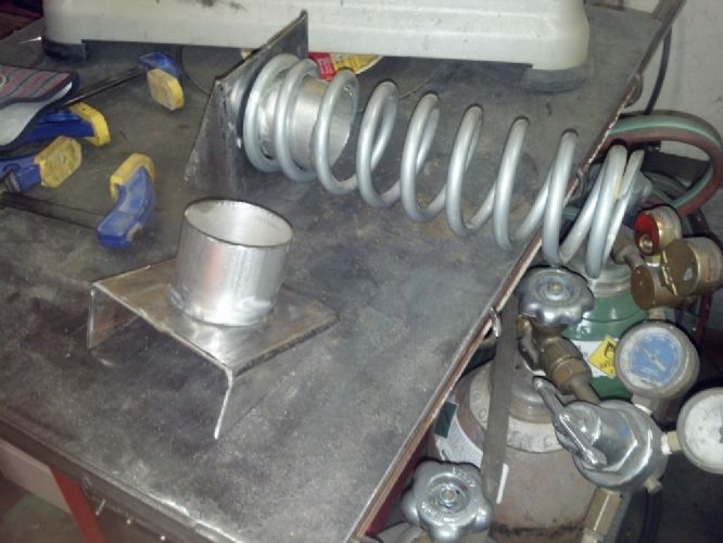
Made 2 upper spring frame brackets today from some angle iron and 2 1/2 inch exhaust pipe. The spring is a coil-over type, but will be used as a regular coil spring. This is because the Mustang lower trailing arm has a small pad for a coil spring with only a 2 5/8 inch inside diameter.
 February 1, 2013 at 8:23 pm #253090
How much of that pipe is really needed to hold the springs in place? I ask because it looks to me like if you give ’em two coils each with the springs uncompressed, you’re gonna have scant travel once the weight is on ’em.
Oh, yeah, and again: Holy crap you do clean, nice work!
edsnova2013-02-01 20:26:12February 2, 2013 at 11:54 am #253091I will need 5 inches of clean travel at the differential, which is only 3.6 inches of compression at the spring. Tons of room. The main driver for the 5 inches of travel is a result of the shock absorber choice. I had to find a shock that would compress to 10 inches or less and I wanted a style that had mounting eyes at both ends. I hate shocks with screw threads at the top, they always rust and are a PIA to remove. Looking at the main list from Monroe, style 33121 was the only one that fit the requirements. As it turns out, this is a 1963-1970 Corvette rear shock, hope it works out.
Here is the complete Monroe catalog….
http://www.monroe.com/assets/downloads/english/08_MountingLengthSheet.pdfFebruary 3, 2013 at 4:07 pm #253092Made some lower trailing arm mount plates today, one of the two plates will also be lower mount point for the rear shock.
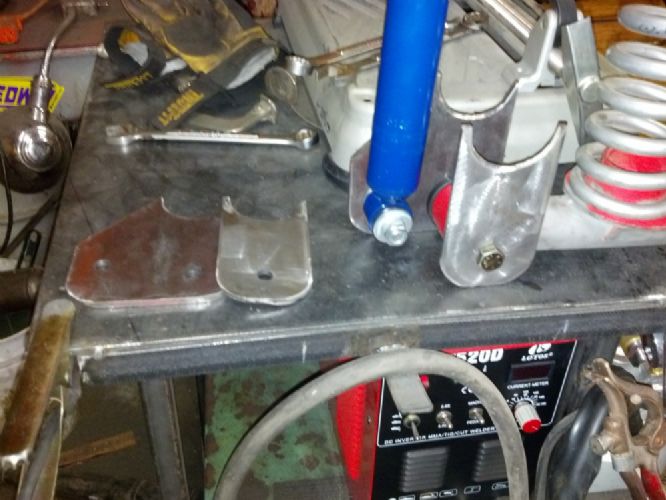
Here is one set of rear suspension pieces. Still missing is the top shock mount.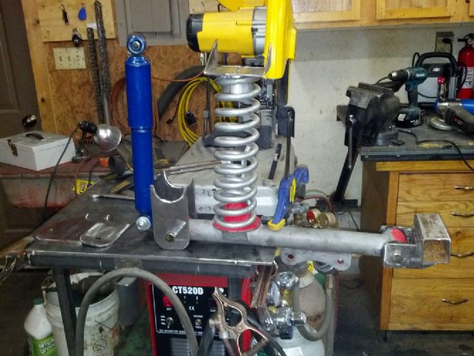 February 3, 2013 at 4:47 pm #253093
Hmm. That looks like some sort of suspension system, would be my guess.
Stagger the shocks?
edsnova2013-02-03 16:48:03February 3, 2013 at 6:36 pm #253094Vertical shock placement for “ride”…angled for increased handling…or find a happy medium.
Definitely looking good.Bill Ascheman
Fiberfab Ford
Modified 5.0, 5sp., 4:11
Autocross & Hillclimb
"Drive Happy"February 3, 2013 at 10:47 pm #253095The arms are Fox Body Mustang lower rear control arms that I got cheap on Ebay. Here’s the item on Summit
http://www.summitracing.com/parts/sum-790000b-w/media/images
I wanted a lower arm strong enough to mount a coil spring on. The semicircular cuts in the plates get welded to the rear axle tubes after I grind off the leaf spring mounts.
February 7, 2013 at 1:10 pm #253096Tacked the rear suspension to the frame. Really close to having a rolling frame. Next is to weld front crossmember to frame rails.
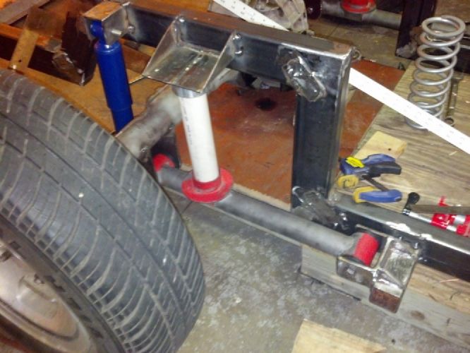
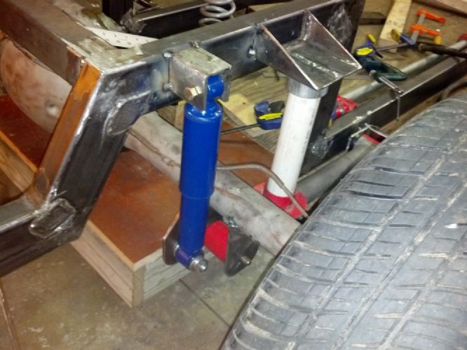 February 7, 2013 at 3:02 pm #253097
I have never built a frame, and am thoroughly enjoying watching your progress, so this is a question – not a criticism. Wouldn’t it be better to turn the upper shock mount 90 degrees to better allow movement?
February 7, 2013 at 4:14 pm #253098Very Nice !!
Bill Ascheman
Fiberfab Ford
Modified 5.0, 5sp., 4:11
Autocross & Hillclimb
"Drive Happy"February 8, 2013 at 6:45 pm #253099I considered the position of the upper shock mount, but turning it 90 degrees would have meant putting a hole through the frame and using a longer bolt. I moved the rear through the entire range of extension and it did no seem to bind at all. Notice, however, that the upper shock mount is still only tacked in place, thus giving me a chance to change the design.
February 8, 2013 at 7:01 pm #253100A rolling frame! It felt great pushing this out into the sunshine. Next will be to fabricate the engine mount frame brackets and ditto for the transmission mount.
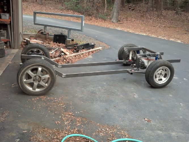
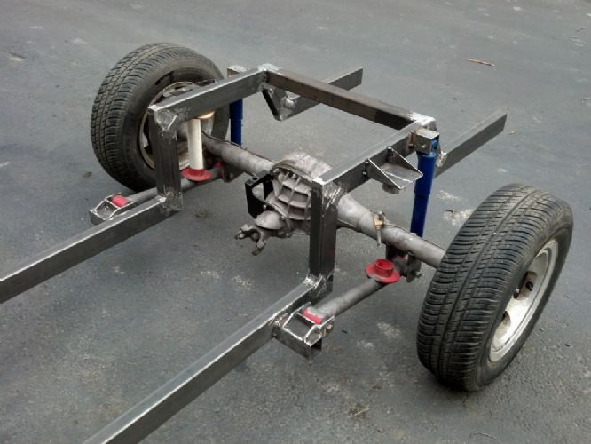
Complete with my PVC rear spring simulator….
My car builder friend lent me these 16X7 4X10⁸ wheels (front) that came off a 2000 or so Cougar. They cleared the upper ball joint but rubbed on upper A-Arm at full turn. I cut off the outside lip from the outer half of the A-Arm and they clear fine. With a 5 1/2 offset, they are set in more and will track better than those 13’s in the back. The tires are 205/55R16. I could go to 50 series to have the same diameter as the original 13’s.February 12, 2013 at 6:27 pm #253101Fabricated and welded in engine mounts and transmission mount. They are made from the old frame mounts, cut off extra and extended to fit. Just tack welded in for now. Good thing, for I tried on the main body and discovered that I needed to move the engine forward one inch. All moved now….
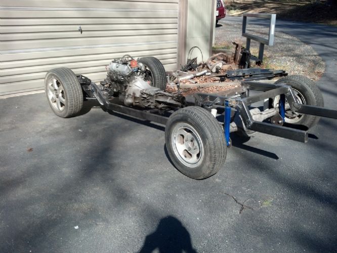
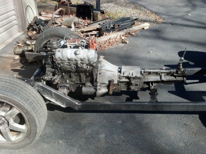
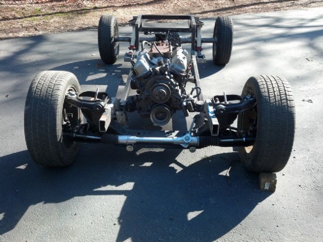
Engine as shown is missing fan, carb, exhaust manifolds and alternator. Getting the alternator inside the bonnet sides will be quite a challenge. The stock location of the alternator stuck outside at least 6 inches to the right (passenger side). Overall it looks like a natural for this very narrow car.February 12, 2013 at 7:43 pm #253102I’d think if the part is not available commercially you could fab one up. And since you’re not running any sissy A/C, PS or other belt-driven detritus, you’ll make easy work of it….
Man, that baby looks wiiiide.
February 13, 2013 at 8:50 am #253103I ordered one of these yesterday. Not only smaller, but I can get rid of the external regulator.
-
AuthorPosts
- You must be logged in to reply to this topic.
